In addition to sharing most of the parts and features of the Grumman version of the Blue Sky Sun Visor, the RV-10 sun visors are also simple and quick to install with a minimum of tools and requires minimal mechnical ability.
RV-10 Sun Visor Installation
RV-10 Installation Guide
- Portable drill - 9/64" drill bit -5/64" Drill bit - 100 Degree Countersink Bit
A. See the Parts List Photo at the end of these instructions for the names of the visor parts referred to in the following instructions.
B. Loosen the Clamp Knob so that the Visor Screen slides easily on the Support Rod. Remove the Rod End Cap and slide the Visor Screen off of the Support Rod and set the Visor Screen aside.
C. Turn the support rod so that it is in line with the swivel cylinder.
Step two:
Mount Installation
A. We recommend that you install the co-pilot side visor first. Measure a spot 14.5" from the center of the windshield center brace and make a mark on the forward side of the windshield/door frame. This spot should be about the level with the upper edge or the side window (door window)
B. Put the 5/64" drill bit in your portable drill.
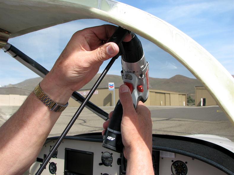
C. With the previously removed Swivel Cylinder/Support Rod assembly in one hand and with the brass insert on the Mount Block facing toward the rear of the plane, push the entire assembly upward and rearward against the windshield/door frame to compress any fabric to the extent possible. While keeping the upward and rearward pressure on the assembly, drill a pilot hole at a slight upward angle through the center of the threaded brass insert with the portable drill as shown in the photo. Proper location of this hole is essential to assure that the entire assembly is free of movement when visors are in use.
Drilling the Pilot Hole
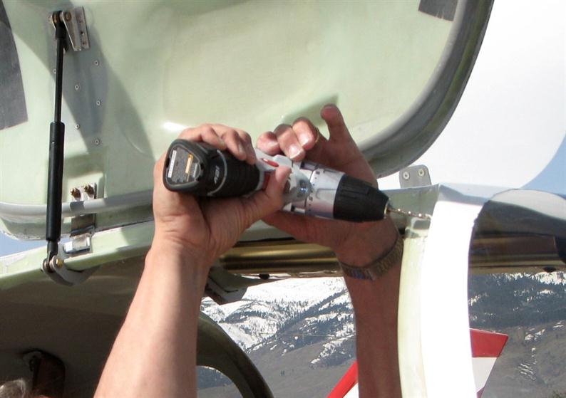
D. Once the pilot hole is completed, enlarge the pilot hole with the 9/64" bit from the outside as shown. Keep the drill on a slight downward angle to maintain the hole angle the same as the pilot hole drilled earlier.
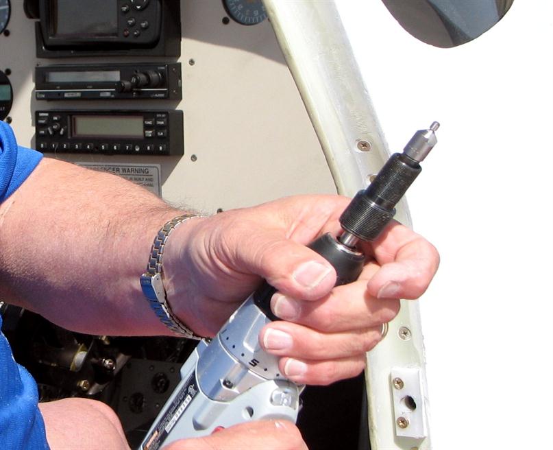
E. Using the portable drill and a 100 degree countersink bit (shown below), bevel the edges of the hole enough to allow the Tinnerman washer to sit flush with the surface of the door/windshield frame.
F. Take care to avoid snagging the fabric with the drill bit. We suggest some tape around the edges of the hole to protect the fabric from the drill bit.
Drill the Mount Block Screw Hole
Piloted Countersink Bit
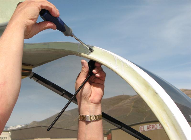
G. Insert the #6-32 X 1" flat head countersunk stainless Mount Block Screw through the Mount Block Washer and the windshield frame as shown until it is properly threaded into the brass insert. Take care to avoid cross threading the screw and brass insert.
Attach the Mount Block
H. Tighten the Mount Block Screw as shown above until the Mount Block has fully compressed any fabric between the Mount Block and the airframe and it is free of fore and aft or side-to-side movement.
Note: If there is some movement that can’t be removed by simply tightening the Mount Block Screw, loosen the screw and insert a small thin wood or plastic shim between the Mount Block and airframe at the correct contact points and then re-tighten the screw until movement is gone.
Step Three:
Visor Installation and Re-Assembly
A. Separate the parts of the Visor Screen Assembly by removing the Clamp Knob and Clamp Knob Washer and unscrewing the Clamp Plate Screw from the Front Clamp Plate. Remove the protective paper by lifting at one of the corners and peel it off both sides.
B. With the protective paper removed, re-assemble the co-pilot side Visor Screen Assembly by placing the Visor Screen on a table with the larger end to your left and the smaller tabbed end on the right. Place the Rear Clamp Plate under the smaller end of the Visor Screen and align the smaller holes of Visor Screen and the Rear Clamp Plate. Then place the Front Clamp Plate on top of the Visor Screen so the smaller countersunk hole is directly above the smaller hole in the Visor Screen. Insert the ½" long Clamp Plate Screw in the hole and tighten enough to have solid contact between all 3 pieces. Then align the 3 larger holes in the Front Clamp Plate, the Visor Screen, and the brass insert in the Rear Clamp Plate. Place the Clamp Knob Washer over the larger hole and insert the Clamp Knob through the washer and engage the threads in the Rear Clamp Plate.
C. Tighten the Clamp Knob about 5 turns and slide the Visor Screen assembly onto the Support Rod. Swivel the Support Rod so that it is in a horizontal position. Then push the Support Rod through the 1/4" hole in the Rear Clamp Plate until it contacts the vinyl Support Rod Spacer at the base of the Support Rod.
D. With the Visor Screen assembly hanging loosely on the Support Rod, grasp the larger end of the Visor Screen and push it up and down. It should move with some resistance in a vertical plane. This function allows the top of the Visor Screen to more closely align with the top of the windshield to provide better screening as the Visor Screen is moved along the Support Rod.
E. Then tighten the Clamp Knob just enough so that the Visor Screen will not rotate or slide on the Support Rod. When tightened enough, a ½ turn of the Clamp Knob should be sufficient to slide the Visor Screen on the Support Rod. Do not over tighten the Clamp Knob to prevent deforming the Rear Clamp Plate.
F. Replace the vinyl Rod End Cap and installation and assembly of your co-pilot side Blue Sky Sun Visors is finished.
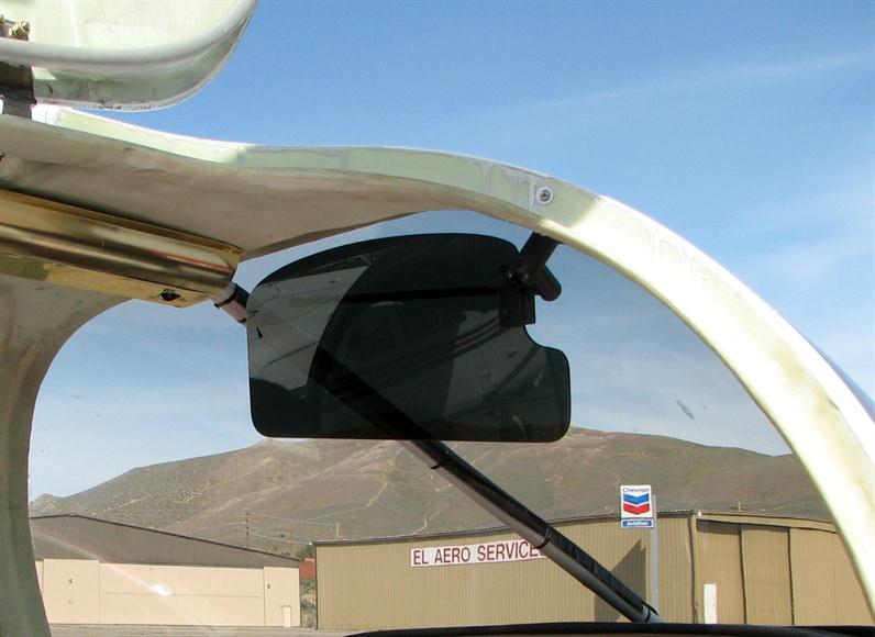
Co-Pilot Visor Installed
Step Four: Pilot Side Installation
Repeat Steps 1, 2, & 3 above for installation of the pilot side visor except the larger end of the visor screen will be on the right when attaching the Front and Rear Clamp Plates.
A printed version of the instructions above can be obtained by selecting the following link: